تأثير سطحي

الأثر السطحي skin effect هو ظاهرة ناجمة عن سعي التيار الكهربائي العالي التواتر للجريان في طبقة سطحية رقيقة من الناقل، وهو يعرف بأثر كلڤن kelvin نسبة للعالم اللورد كلڤن كما يُعرف بالأثر الجلدي أو الأثر القشري.
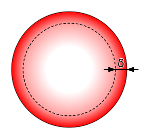
إذا كان جريان الكهرباء يتم في اتجاه واحد مستمر فإن التيار الكهربائي يتوزع بانتظام على سطح مقطع عرضي لناقل منتظم، أي أن كثافة التيار، وهي شدته في وحدة المساحة، تكون واحدة في كل نقطة من سطح المقطع. ولا يحدث هذا الانتظام البسيط في حالة تيار متناوب بل تكون كثافة التيار قرب السطح الخارجي للناقل أكبر مما هي عليه في مركزه، ويزداد الفرق بينهما كلما ازداد تواتر التيار. ويكون هذا الأثر ضئيلاً جداً إذا كان هذا التواتر منخفضاً. أما في حالة التواترات العالية، عندما يصبح طول الموجة داخل مادة الناقل من مرتبة أبعاد مقطع الناقل أو أصغر منها فإنه يمكن أن يُعد جريان التيار مقتصراً على طبقة سطحية (قشرة) من الناقل رقيقة نسبياً، ويطلق على ثخن هذه الطبقة عمق النفوذ أو ثخن القشرة دلتا.
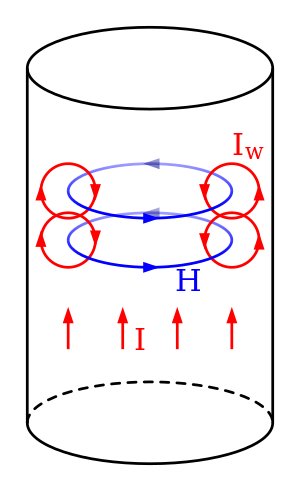
ففي حالة ناقل أسطواني مستقيم يمر فيه تيار متناوب، يولد هذا التيار في الناقل حقلاً تحريضياً مغنطيسياً ، ويظهر في كل نقطة حقل كهربائي تحريضي محرِّك فإذا كان الحقل الكهرالدي، فإن الحقل الكهربائي الكلي يساوي وترتبط كثافة التيار بالحقل بالعلاقة حيث تمثل σ ناقلية (موصلية) conductivity مادة الناقل. وينتج أن:
وتؤدي الدراسة الرياضية اعتماداً على معادلات مكسويل إلى العلاقتين الآتيتين
حيث يدل ro على نصف قطر السلك الناقل، ويدل r على بعد النقطة المعتبرة عن محور الناقل، ويدل Jo Eo على الحقل الكهربائي وكثافة التيار عند سطح الناقل. أما σ فيدل على عمق النفوذ أو ثخن قشرة الناقل ويساوي:
حيث f تواتر (تردد) التيار الكهربائي، و u السماحية المغنطيسية permeability وتبين العلاقتان (1) و (2) تغير كل من الحقل الكهربائي وكثافة التيار بتغير بعد النقطة المعتبرة عن محور الناقل r<r0. وتظهر العلاقة (3) ما سبق شرحه من أنه كلما كبرت الناقلية σ وازداد تواتر التيار f نقص عمق النفوذ أو ثخن القشرة، وأن هذا الثخن ينتهي إلى∞ إذا كان التيار مستمراً (متصلاً) أي f يساوي الصفر، أي يزول الأثر السطحي. كذلك تظهر العلاقة (3) أن هذا الأثر يصبح كاملاً عندما ينتهي التواتر إلى اللانهاية.
وينجم عن الأثر السطحي أن تكون مقاومة ناقل ما من حالة تيار متناوب أكبر مما هي في حالة تيار مستمر، ذلك لأن سطح المقطع الفعال للناقل يصغر في الحالة الأولى، وينجم عن صغر المقطع الفعال أيضاً أن مقاومة الناقل R تتغير بتغير تواتر التيار وتزداد بازدياده. ففي حالة ناقل أسطواني مستقيم تتغير R مع تواتر التيار وبالتالي مع وفقاً للخط البياني المبين في الشكل. وهناك صيغ تجريبية أولية تمكن من حساب المقاومة R من أجل تواتر معين f انطلاقاً من المقاومة Ro في حالة تيار مستمر. فعلى سبيل المثال، من أجل ناقل مستقيم بعيد عن أي كتلة مغنطيسية يكون:
حيث S: مقطع الناقل (ليس دائراياً بالضررورة). و P: محيط مقطع الناقل. ولكن حساب المقاومة يصبح مستحيلاً من الناحية العملية إذا كان الناقل في جوار كتل ذات مغنطيسية حديدية، إذ تصبح مسارات خطوط التحريض وبالتالي مسارات التيار معقدة جداً.
ولما كان جريان التيار العالي التواتر يقتصر على الجزء السطحي من السلك الناقل فإن هذه الأسلاك تُلبس بمادة ذات ناقلية عالية أو تُستعمل نواقل مجوفة أو نواقل مكونة من أسلاك دقيقة معزول بعضها عن بعض فتكون سطوح هذه الأسلاك أكبر كثيراً من سطح سلك وحيد مقطعه يساوي المقطع الكلي لجميع الأسلاك الدقيقة.[1]
السبب

التخفيف
أمثلة

Mn-Zn - magnetically soft ferrite
Al - metallic aluminium
Cu - metallic copper
steel 410 - magnetic stainless steel
Fe-Si - grain-oriented electrical steel
Fe-Ni - high-permeability permalloy (80%Ni-20%Fe)
| Conductor | Skin depth (μm) |
|---|---|
| Aluminum | 0.80 |
| Copper | 0.65 |
| Gold | 0.79 |
| Silver | 0.64 |
| Frequency | Skin depth (μm) |
|---|---|
| 60 Hz | 8470 |
| 10 kHz | 660 |
| 100 kHz | 210 |
| 1 MHz | 66 |
| 10 MHz | 21 |
| 100 MHz | 6.6 |
Skin effect reduction of the self inductance of a conductor
الحث في طول الكابلات المحورية

Characteristics of telephone cable as a function of frequency
Representative parameter data for 24 gauge PIC telephone cable at 21 °C (70 °F).
| Frequency (Hz) | R (Ω/km) | L (mH/km) | G (μS/km) | C (nF/km) |
|---|---|---|---|---|
| 1 | 172.24 | 0.6129 | 0.000 | 51.57 |
| 1k | 172.28 | 0.6125 | 0.072 | 51.57 |
| 10k | 172.70 | 0.6099 | 0.531 | 51.57 |
| 100k | 191.63 | 0.5807 | 3.327 | 51.57 |
| 1M | 463.59 | 0.5062 | 29.111 | 51.57 |
| 2M | 643.14 | 0.4862 | 53.205 | 51.57 |
| 5M | 999.41 | 0.4675 | 118.074 | 51.57 |
انظر ايضاً
- Proximity effect (electromagnetism)
- Penetration depth
- Eddy currents
- Litz wire
- Transformer
- Induction Cooking
- Induction heating
- Magnetic Reynolds number
الهوامش
- ^ توفيق قسام. "الأثر السطحي". الموسوعة العربية.
المصادر
- Chen, Walter Y. (2004), Home Networking Basics, Prentice Hall, ISBN 0-13-016511-5
- Hayt, William (1981), Engineering Electromagnetics (4th ed.), McGraw-Hill, ISBN 0-07-027395-2
- Hayt, William Hart. Engineering Electromagnetics Seventh Edition. New York: McGraw Hill, 2006. ISBN 0-07-310463-9.
- Nahin, Paul J. Oliver Heaviside: Sage in Solitude. New York: IEEE Press, 1988. ISBN 0-87942-238-6.
- Ramo, S., J. R. Whinnery, and T. Van Duzer. Fields and Waves in Communication Electronics. New York: John Wiley & Sons, Inc., 1965.
- Ramo, Whinnery, Van Duzer (1994). Fields and Waves in Communications Electronics. John Wiley and Sons.
{{cite book}}: CS1 maint: multiple names: authors list (link) - Reeve, Whitman D. (1995), Subscriber Loop Signaling and Transmission Handbook, IEEE Press, ISBN 0-7803-0440-3
- Skilling, Hugh H. (1951), Electric Transmission Lines, McGraw-Hill
- Terman, F. E. (1943), Radio Engineers' Handbook, New York: McGraw-Hill. For the Terman formula mentioned above.
- Xi Nan; Sullivan, C. R. (2005), "An equivalent complex permeability model for litz-wire windings", Industry Applications Conference 3: 2229-2235, doi:, ISBN 0-7803-9208-6, ISSN 0197-2618, http://ieeexplore.ieee.org/Xplore/login.jsp?url=http%3A%2F%2Fieeexplore.ieee.org%2Fiel5%2F10182%2F32507%2F01518758.pdf%3Farnumber%3D1518758&authDecision=-203
- Jordan, Edward (1968), Electromagnetic Waves and Radiating Systems, Prentice Hall, ISBN 978-0-13-249995-8
- Vander Vorst, Andre; Rosen, Arye; Kotsuka, Youji (2006), RF/Microwave Interaction with Biological Tissues, John Wiley and Sons, Inc., ISBN 978-0-471-73277-8


